![]()
Operating principle and optical path
 |
|
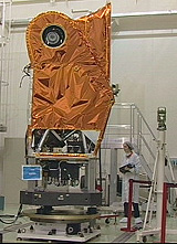
HRG camera during integration
(october 2000) |
The camera acquires imagery using a pushbroom scanning
technique. The wide-field optics form the image of the ground patch on a line
of detectors in the focal plane.
Signals are read out sequentially from the linear arrays of detectors, thus
building up the image line by line through the forward motion of the satellite.
Beamsplitters and prisms separate incoming beams into different spectral regions and direct them onto six rows of detectors simultaneously.
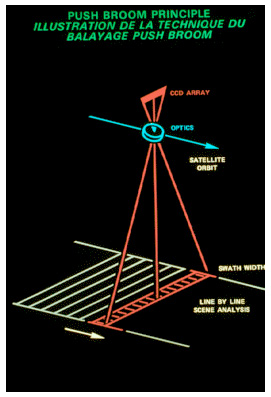
Pushbroom scanning
The HRG instrument's steerable mirror enables vertical and oblique viewing:
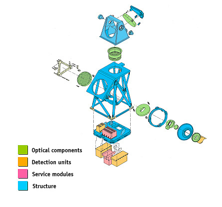
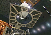
HRG instrument architecture
The main components of the HRG instrument are:
- a stable structure supporting its mechanisms
- an optical subassembly
- detection electronics
- ancillary electronics
HRG instrument integration
On all previous SPOT satellites, optical components
were integrated using theodolites.
On SPOT 5, this simple method was not precise enough to meet performance objectives
for the HRG instrument in terms of resolution.
Consequently, theodolites were used for initial, relatively coarse alignment
of the components. Precise alignment was obtained by measuring the wavefront
directly by interferometry to correct residual defects.
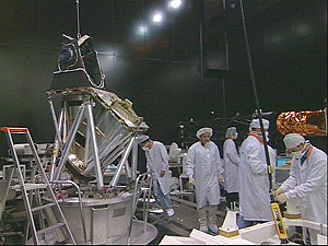
The HRG instrument during integration
Technical data
|
HRG technical data
|
|||
| Mass | 356 Kg | ||
| Maximum power (depending on mode) | 344 w | ||
| Dimensions |
2.65 x 1.42 x 0.96 m |
||
| Oblique viewing angle |
+/- 27 degrees |
||
| Focal length |
1.082 m |
||
| Field of view |
+/- 2 degrees |
||
| Performance |
P |
B1 B2 B3 |
SWIR |
| Spectral range (panchromatic band) |
0,49-0,69 microns |
B1 0.50-0.59 |
1.58-1.75 microns |
| Detectors per line | 12000 | 6000 | 3000 |
| Number of lines | 2 offset | 3 registered | 1 |
| Detector pitch | 6.5 microns | 13 microns | 26 microns |
| Integration time per line | 0.752 ms | 1.504 ms | 3.008 ms |
| Ground sample distance | 5 x 5 m single image 3,5 x 3,5 dual image |
10 x 10 m | 20 x 20 m |
| Signal-to-noise ratio |
170
|
240
|
230
|
| Modulation transfer function | > 0.2 | > 0.3 | > 0.2 |
 Integrating the HRG1 instrument:
video (1,01 Mb)
 The
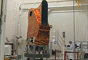
HRG1 instrument after integration:
The
HRG1 instrument after integration:
video (975 kb)
![]() Structure
Structure
Optical
subassembly
Detection
electronics
Ancilliary
electronics